115 Results
View results:
Sort by:

The National Building Code of Canada (NBC) 2020 Article 4.1.8.7 provides a clear procedure for earthquake methods of analysis. The more advanced method, the Dynamic Analysis Procedure in Article 4.1.8.12, should be used for all structure types except those that meet the criteria set forth in 4.1.8.7. The more simplistic method, the Equivalent Static Force Procedure (ESFP) in Article 4.1.8.11, can be used for all other structures.

When wind-induced surface pressures on a building are available, they can be applied on a structural model in RFEM 6, processed by RWIND 2, and used as wind loads for static analysis in RFEM 6.

RWIND 2 and RFEM 6 can now be used to calculate wind loads from experimentally measured wind pressures on surfaces. Basically, two interpolation methods are available to distribute pressures measured in isolated points across the surfaces. The desired pressure distribution can be achieved using the appropriate method and parameter settings.

Both the determination of natural vibrations and the response spectrum analysis are always performed on a linear system. If nonlinearities exist in the system, they are linearized and thus not taken into account. They are caused by, for example, tension members, nonlinear supports, or nonlinear hinges. This article shows how you can handle them in a dynamic analysis.

The response spectrum analysis is one of the most frequently used design methods in the case of earthquakes. This method has many advantages. The most important is the simplification: It simplifies the complexity of earthquakes so far that the design can be performed with reasonable effort. The disadvantage of this method is that a lot of information is lost due to this simplification. One way to moderate this disadvantage is to use the equivalent linear combination when combining the modal responses. This article explains this option by describing an example.

Spreadsheet programs like MS EXCEL are very popular with engineers because they allow you to simply automatize your calculations and quickly output the results. Therefore, combining MS EXCEL used as a graphical interface with Dlubal's WebService API is an obvious choice. By using the free xlwings library for Python, you can control EXCEL, and read and write values. The functionality is described in the following, using an example.

Line releases are special objects in RFEM 6 that allow structural decoupling of objects connected to a line. They are mostly used to decouple two surfaces that are not rigidly connected or transferring only compressive forces at the common boundary line. By defining a line release, a new line is generated at the same place which transfers only the locked degrees of freedom. This article will show the definition of line releases in a practical example.

Windbreak structures are special types of fabric structures which protect the environment from harmful chemical particles, abate wind erosion, and help to maintain valuable sources. RFEM and RWIND are used for wind-structure analysis as one-way fluid-structure interaction (FSI).
This article demonstrates how to structural design windbreak structures using RFEM and RWIND.

The “Modal Analysis” add-on in RFEM 6 allows you to perform modal analysis of structural systems, thus determining natural vibration values such as natural frequencies, mode shapes, modal masses, and effective modal mass factors. These results can be used for vibration design, as well as for further dynamic analyses (for example, loading by a response spectrum).

Modal analysis is the starting point for the dynamic analysis of structural systems. You can use it to determine natural vibration values such as natural frequencies, mode shapes, modal masses, and effective modal mass factors. This outcome can be used for vibration design, and it can be used for further dynamic analyses (for example, loading by a response spectrum).
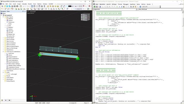
Webservice is a communication between machines and programs. This communication is provided via the network and can, therefore, be used by any program that can send and receive strings via the HTTP protocol. RFEM 6 and RSTAB 9 provide an interface based on these cross-platform webservices. This tutorial shows the basics using the VBA programming language.

Structures in RFEM 6 can be saved as blocks and reused in other RFEM files. The advantage of dynamic blocks with respect to non-dynamic blocks is that they allow interactive modifications of the structural parameters as a result of modified input variables. One example is the possibility to add structural elements by changing only the number of bays as an input variable. This article will demonstrate the aforementioned possibility for dynamic blocks that are created by scripting.

According to EN 1992-1-1 [1], a beam is a member of which the span is no less than 3 times the overall section depth. Otherwise, the structural element should be considered as a deep beam. The behavior of deep beams (that is, beams with a span less than 3 times the section depth) is different from the behavior of normal beams (that is, beams with a span that is 3 times greater than the section depth).
However, designing deep beams is often necessary when analyzing the structural components of reinforced concrete structures, since they are used for window and door lintels, upstand and downstand beams, the connection between split-level slabs, and frame systems.

Defining the appropriate effective length is crucial in obtaining the correct member design capacity. For X-bracing that is connected at the center, engineers often wonder if the full end-to-end length of the member shall be used, or whether using half of the length to where the members are connected is sufficient.This article outlines the recommendations given by the AISC and provides an example on how to specify the effective length of the X-braces in RFEM.

The effects due to snow load are described in the American standard ASCE/SEI 7-16 and in Eurocode 1, Parts 1 through 3. These standards are implemented in the new RFEM 6 program and the Snow Load Wizard, which serves to facilitate the application of snow loads. In addition to this, the most recent generation of the program allows the construction site to be specified on a digital map, thus allowing the snow load zone to be imported automatically. These data are, in turn, used by the Load Wizard to simulate the effects due to the snow load.

Imperfections in construction engineering are associated with production-related deviation of structural components from their ideal shape. They are often used in a calculation to determine the equilibrium of forces for structural components on a deformed system.

The reinforced concrete design for fire situations is carried out according to the simplified method based on EN 1992-1-2, Clause 4.2. The "zone method" described in Annex B.2 is used: The cross-section is subdivided into a number of parallel zones of equal thickness, and their temperature-dependent compressive strength is determined. The reduced load-bearing capacity in the event of fire exposure is thus represented by a reduced structural component's cross-section with reduced strengths.

The "4.0 Results - Summary" table displays the infinity norm at the end of the load case results. The norm is used to estimate the largest eigenvalue of a structure. The largest eigenvalue of a structure is estimated by numerical analysis, as accurate determination can be very time-consuming.
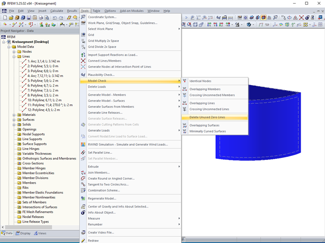
When creating or importing a model, it can happen that lines with a length of zero are created.

In RFEM and RSTAB, you can visually check or display the materials used for members in the wireframe and solid models.
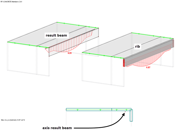
Although the design of downstand beams is usually carried out on a member model, a result beam can be used to perform the design on a model with only surfaces.
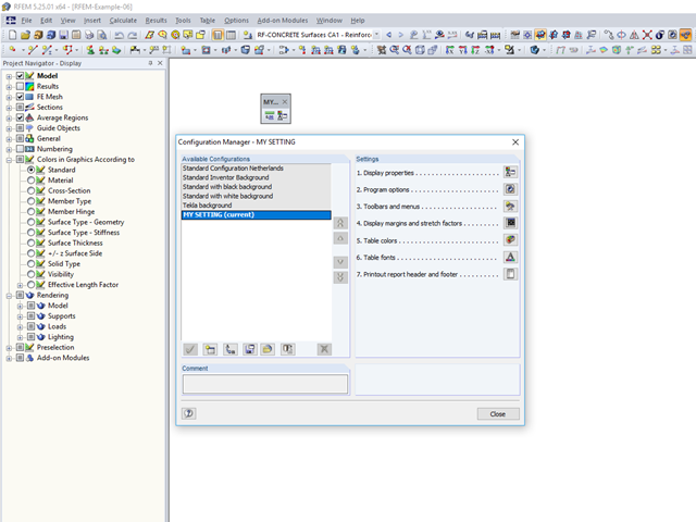
An individual user‑defined workspace can increase your productivity and make your daily work easier. This is why many users take the opportunity to adjust the toolbars in RFEM and RSTAB and to create their own toolbars containing the most frequently used commands.

In RF‑/CONCRETE Columns, different methods are available for defining the minimum longitudinal reinforcement. The minimum reinforcement can be selected according to the design standard used and/or specified by the user.
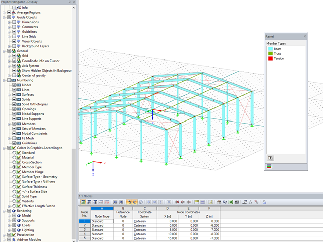
In RFEM and RSTAB, you can now also display and check the types of members used visually, by means of colors. To do this, an option has been integrated into the Display Navigator.

When calculating foundations according to EC 7 or EC 2, different foundation types or sizes are usually used in one object. However, boundary conditions like the soil parameters, the materials for foundations, concrete covers, and the load combinations selected for design remain the same for all foundations, as a rule.
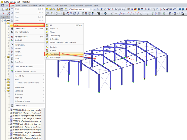
When you finish modeling a structure, it can often happen that some unused nodes remain in the model.

DXF layers of ground plans cannot be used directly in FEA programs because only the outer contours of the elements (walls, ceilings, and so on) are available in the drawing. The FEM programs require system axes, but only the outer contours of the elements (walls, ceilings, and so on) are available in the DXF drawing.

In order to detect the governing internal forces of a plate, a checkerboard loading is commonly used. Since it is not necessary to divide the surface into individual load segments, loading is usually carried out by means of free rectangular loads. In the case of many loads, the normal load display can become somewhat confusing.

For a quick overview of the cross‑sections used, you can show the members in color sorted by cross‑section. Use the right mouse button in the work window to select "Colors in Graphics According to" → "Cross -Sections" from the shortcut menu. In the current program versions, you can use a panel with an editable color scale for this.
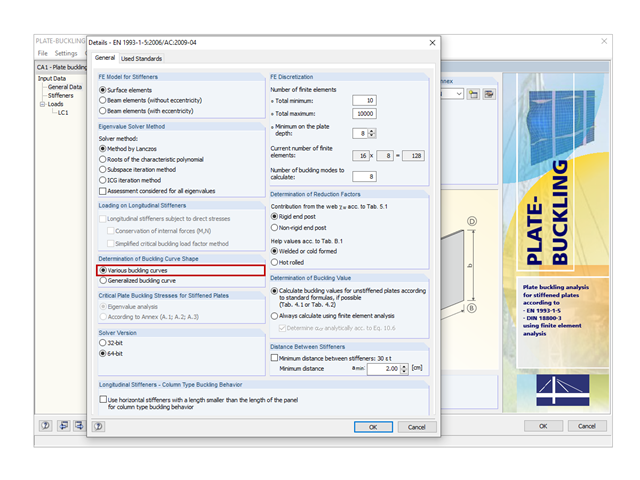
In PLATE‑BUCKLING 8, two options in the detail settings can be used to calculate the reduction factors of plate buckling.